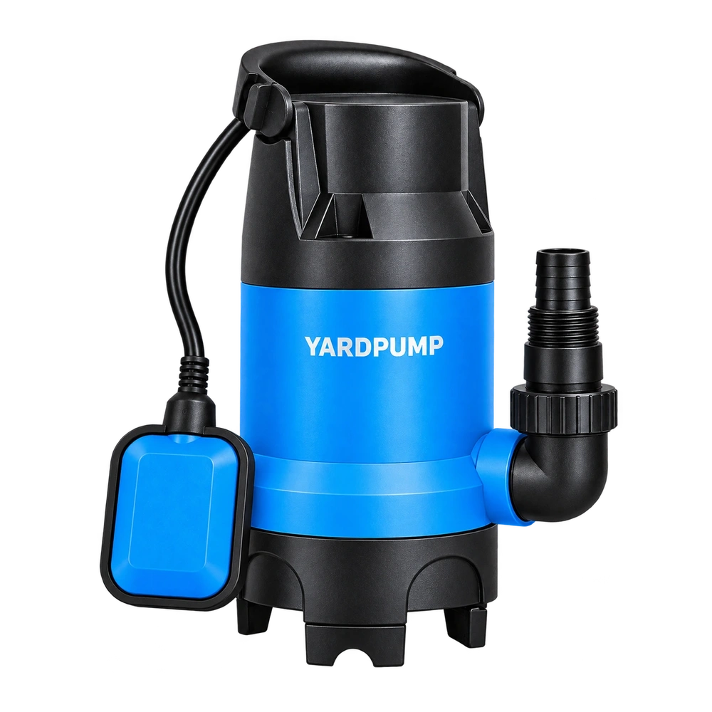
Suppose a distributor receives hoses for a small submersible drainage pump. Each hose fits the outlet fitting, and the clamp has the same nominal size as the approved sample. During operation the hose creeps away from the fitting. Before tightening the screw again, check how far the hose was pushed on and where the clamp actually grips. A clamp can feel tight while squeezing a section of hose that the fitting does not support.
A fitted diameter says little about axial position
A barbed or ridged shank uses the geometry of the fitting, the matched hose wall and the specified clamp to retain the hose. The effective clamping zone depends on the shank shape, available support, hose construction and band width. A half-inserted fitting can leave the band compressing the part of the hose beyond the shank. A band across the wrong step or too close to the cut end can also concentrate load on one edge. Fittings differ in their ridges, smooth lands and stops. A rule such as putting every clamp behind a barb is no substitute for the assembly drawing.
Starts, line motion and unusual restriction can add pressure or external pull to the connection. Shallow engagement reduces the intended contact area. If the hose is moved around after assembly, the load can end up on the pump outlet. Tightening a misplaced clamp can flatten the hose or distort a plastic fitting without correcting either problem. Tightening torque may matter for the approved combination, but it does not locate the band.
Give inspectors a mark they can see
Ask for the identities of the approved fitting, hose and clamp. The assembly drawing should show the hose end position, insertion depth, band centre relative to the end, band width and applicable tolerances. On an approval sample, lay the unassembled hose beside the shank to see where the support ends. A visible insertion mark and band alignment mark can then make the assembled position easy to check. Confirm the marks against the real geometry on a first article, using a suitable gauge or agreed sectioned sample. A mark should remain visible and should not cover damage or change the hose surface.
Here is an illustrative geometry. Suppose the approved clamp zone extends 8 to 20 mm away from the end of the hose and the band is 8 mm wide. Its centre at 13 mm puts the band between 9 and 17 mm, inside the zone. Shift the centre to 20 mm and the band covers 16 to 24 mm; a portion now extends outside, even though the diameter and feel of the screw have not changed. Use the supplier drawing for the real values. Look for a skewed band, cuts at its edge or a tight bend next to the outlet that keeps pulling the hose outward.
Check assembly and retention separately
Inspect placement and dimensions with the assembly unpressurized. Then have qualified staff verify the required sealing and retention on a protected test stand under the approved procedure. Record component revisions, assembly method, test medium, pressure conditions and whether the marks moved. Stop, isolate power and relieve retained pressure before approaching for a closer inspection. If the plan includes a destructive pull-off or pressure test, agree how specimens are selected and removed from stock afterward. Do not pull on a pressurized hose by hand to check its grip.
If the customer assembles the outlet, include a clear picture of orientation and clamp position with the kit. For factory-fitted assemblies, follow first-article approval with batch identification and change checks. An altered band width, shank stop or hose wall can affect an assembly even when all nominal diameters stay the same. This method is for drain hose connections approved for clamping. Crimped and proprietary quick connectors have their own assembly and inspection instructions.
Frequently asked questions
Would two clamps be more reliable than one?
Use the approved count and spacing. On a short shank, a second band may squeeze unsupported hose or move the first band out of its proper zone.
Can I copy the insertion mark from a used hose?
A used end may have stretched, worn or taken a permanent set. Set the mark from the approved drawing and confirm it on an undamaged specimen.
Does a leak-free test prove that the hose cannot slip off?
No. Sealing and retention are distinct. Look for movement as well as leaks under the approved conditions, and record each result separately.