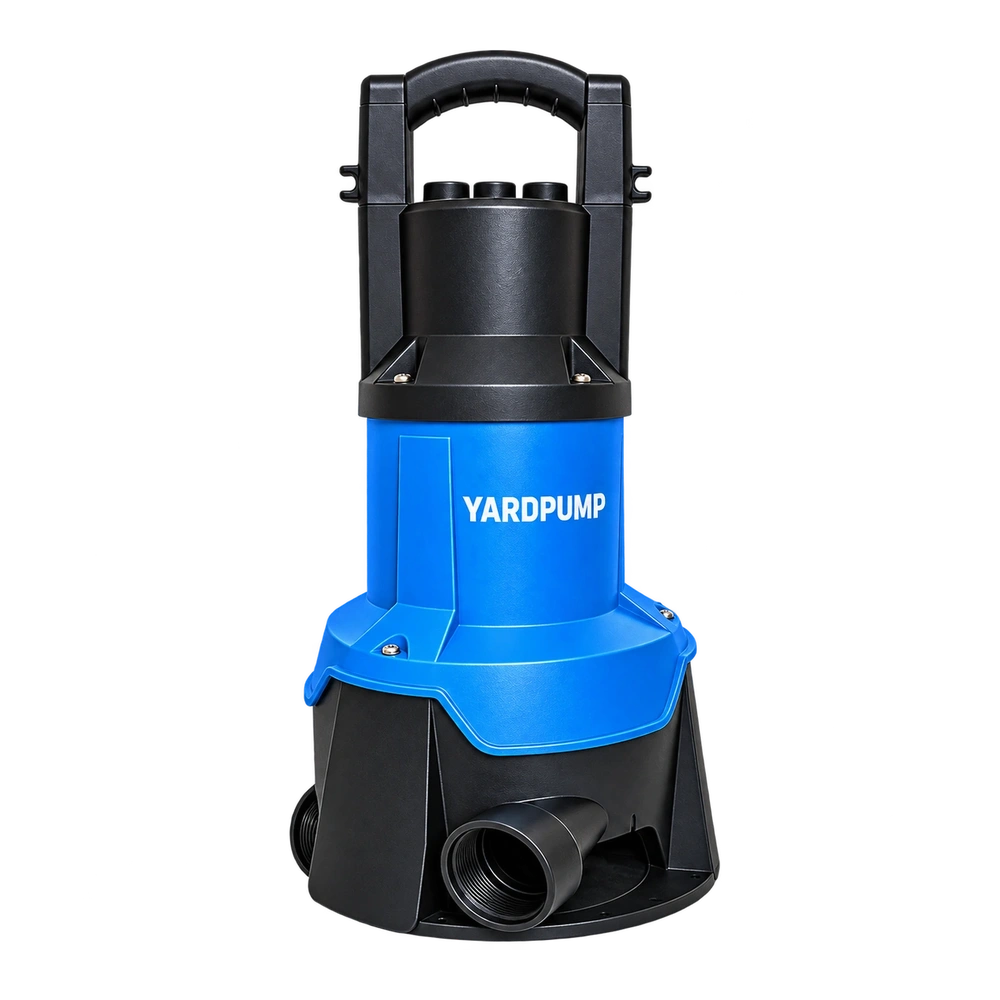
As a discharge valve closes, one centrifugal pump may draw less current. On another setup, the change can be small or the readings can fluctuate. An ammeter is measuring the electrical response of the motor at its new duty. Use voltage and real power alongside current to tell whether that response is consistent with the pump’s expected load.
Follow the change from the pump curve to the motor
Throttling changes flow, head, impeller torque and efficiency. Motor current also depends on voltage and power factor. A pump may draw less input at reduced flow while internal recirculation or liquid heating becomes less acceptable.
A conventional radial-flow design often needs less shaft power over part of the curve as flow falls. Check the exact curve and design because the trend can differ. Changes in voltage and motor power factor also affect current. A current reading on its own cannot distinguish the motor load from changes in electrical conditions.
For example, with a stable 230 V single-phase supply, 3.2 A at a measured power factor of 0.72 corresponds to about 530 W of real input. A second illustrative reading of 2.7 A at 0.82 gives about 509 W. Current fell by roughly 16 percent while real watts fell by around 4 percent. The two changes need not track each other. Use a meter that measures real power for the supply and load under test.
Use simultaneous readings in a controlled comparison
Measure voltage, current, real input power, flow and head together across only the permitted range. Hold liquid temperature and supply conditions, and stop if the model’s operating boundary is reached.
Log a reference point with the agreed discharge open and a second point within the approved range. Record supply voltage and frequency, motor current, real power and steady flow and head. Observe whether a rise in current occurs together with a voltage dip or with changes in the water delivery. Check unexpected heating, a partly obstructed impeller or an unstable reading through the approved service method. Electrical tests belong with qualified personnel.
Keep the motor and pump limits in the decision
Use the curve and released operating envelope to set the duty, then coordinate protection from measured normal and abnormal conditions.
A normal current measurement tells you about the state observed at the test point. Very low flow can be unacceptable because of poor cooling, internal circulation or vibration even if current looks comfortable. Match the protection and permitted valve range to the specific motor and wet end. For a field complaint, stop comparing amperage across pumps until the voltage, route and duty are known.
Separate startup transients from steady readings. A trace that includes inrush will answer a protection or starting question, while a stable input-power reading belongs with the steady head and flow point. Label these records explicitly. If a protective device operates while the stable current was within the expected range, look at when it acted and which device recorded the event before changing a setting. Multiple faults can look like one low or high steady reading.
Frequently asked questions
Is lower current at the same valve position always more efficient?
Measure flow, head and real watts at matched conditions. A change in load or delivered water can change both current and efficiency.
Why did the amps rise when the supply voltage dipped?
An induction motor’s current can change with voltage, slip and load. Confirm the trend with simultaneous readings and evaluate it against the exact model.
Can I set a protective device using the lowest current seen during the test?
Use the manufacturer's limits and the qualified protection design for the equipment. Include expected starting and operating conditions.