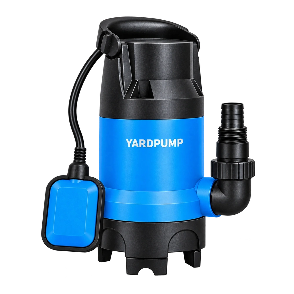
Suppose every outside diameter measured with calipers passes the drawing limits. Once the plastic impeller is mounted, however, one part of its rim runs close to the housing. To judge rubbing risk, check the rim from the installed shaft axis. A caliper gives a size between two points. It does not say whether the outer profile is concentric with the locating bore or how the impeller seats against the real shaft shoulder.
Establish what locates the axis
Some impellers locate on a bore and shaft fit; others also have keys and shoulders that affect seating. Use the locating surfaces on the drawing rather than centring on the apparent rim. Set the part on a qualified mandrel that represents the bore datum and contacts the intended seating surfaces. Do not use enough clamping force to straighten a flexible moulding. An interrupted vane edge may also be unsuitable for a continuous contact reading. Use the specified circular band or measure the maximum envelope at defined angular positions with a suitable noncontact method. Keep the location in the record, so an indicator falling between vanes is not reported as runout.
Run two comparisons. Check the mandrel first. Mount the impeller and log angular readings, then re-index the part on the fixture and repeat. If the high reading follows the part, investigate bore-to-rim geometry. If it stays with the fixture, check the reference and mounting. Now check the same impeller on the intended shaft. A shoulder that has not seated, a key interfering with the hub or debris between faces can move the result. Out-of-roundness, tilt and radial eccentricity may coexist; a single indicator range does not identify them separately.
How a passing diameter can lose clearance
In a simplified example, a circular 80.00 millimetre impeller sits in an 80.80 millimetre bore. When concentric, radial clearance is 0.40 millimetres. Shift the centre of the impeller by 0.25 millimetres relative to the shaft axis and the closest clearance is about 0.15. For a perfect circle with pure eccentricity, the radial indicator range would be about 0.50 millimetres. Housing offset, operating deflection, temperature and bearing movement are not included. These dimensions illustrate a mechanism rather than a manufacturing limit.
Specify diameter, datum and required envelope or runout together. If moulding material, cavity or conditioning state can change, record those conditions and compare like with like. A supplier can pass every diameter while producing a different bore-to-rim result if the only inspection asks for size. Qualified personnel should isolate power and verify it off before mechanical checks. Listening for rubbing on an energized trial is no substitute for establishing the geometry.
Distinguish free and assembled states on the drawing. A designed interference at the bore can alter the outside profile after it is fitted. A clearance-fit mandrel will not necessarily reproduce that state. Use an appropriate gauge for incoming screening and an actual assembly sample to establish the relationship, recording the mounting method for each. Check the housing from its intended locating surfaces as well; an outside shape resting on the table is not an established coaxial datum. Keep maximum diameter, reference-shaft runout and assembled rim readings in separate columns so the fixture error is not repeatedly attributed to the impeller. If the drawing does not define state or datum, have the designer clarify it before using the result to accept a lot.
Frequently asked questions
Can I compare the largest caliper diameter with the casing diameter instead?
That comparison does not establish relative location. Check the rotating envelope and housing position from a common datum.
Why do two mountings on the mandrel give different numbers?
Check seating, bore fit, probe contact and clamping first. Fix poor repeatability before using the measurement to reject a part.
Can I trim the impeller slightly smaller?
It may gain clearance but can alter head, flow and strength. Establish whether the issue is geometry or assembly, then qualify any design change.