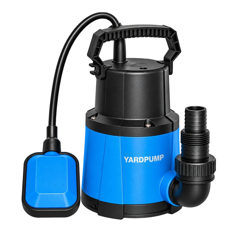
Suppose a clean-water submersible pump is delivering steady flow on a test bench. The head has not changed, and the voltage and current look normal, but the meter keeps displaying negative watts. Set that active power record aside and check the meter's sign convention, the current sensor direction, and the voltage channel. A conventional line-fed pump without regenerative equipment draws energy while it steadily moves water. A sustained negative reading is inconsistent with that condition. A normal current reading does not establish that the power measurement is valid.
Why the current can look right when the watts are wrong
The RMS voltage and current describe magnitudes. Neither value on its own tells you which way energy moves. Active power depends on the voltage and current waveforms together; the instrument averages their instantaneous product. Reversing the current signal can leave its RMS value essentially unchanged while reversing the sign of the power. Taking voltage and current from the wrong combination of channels can also make both the sign and the magnitude misleading.
For illustration, assume a single-phase test at 230 volts and 2 amperes with a power factor magnitude of 0.65. If power into the load is positive, the active input is 230 × 2 × 0.65, or 299 watts. In the ideal case, reversing only the current signal could produce a display of minus 299 watts while both RMS values remain unchanged. These numbers illustrate a sign error. They are not a power or power factor specification for a pump.
Three checks for qualified test personnel
Save the channel layout, sensor identification, ratio setting, and screen capture before anything changes. Identify the part of the run: starting, stopping, or steady operation. Do not take the absolute value in software or use a normal discharge as evidence that the electrical data are sound. Qualified personnel should follow the bench and instrument procedures to isolate and verify the circuit before working on wiring, sensors, or equipment. Use the approved enclosed measurement points to observe a running test.
First, check direction. Confirm that the bench records power flowing into the load as positive. Then compare the actual supply side, load side, and input polarity against the diagrams for that instrument and sensor. Use their markings to interpret the arrow. Second, trace the channels. Check that the voltage input corresponds to the circuit carrying the measured current. Check channel numbers, the sensor range, and the ratio setting. An incorrect ratio generally changes the scale; fixing polarity alone will not resolve that error.
Third, run a controlled comparison. Follow the bench procedure for a documented load with a known direction and expected reading range, then retest the original pump with the same water circuit and supply conditions. Preserve stable flow, head, and power records with the original and corrected configurations. If a negative value appears only during a transition or near zero, examine the averaging window, phase error, and available waveforms separately. A regenerative drive or a bench capable of returning energy can sometimes send power back through the measurement point. Establish that possibility from the system and waveform before attributing a transient to reversed wiring.
Which results can still support acceptance?
Look back to the last point at which the channel configuration was verified and flag tests that may share the error. Independently measured flow and head may remain useful for comparison when their conditions and records are sound. Reconfirm active input power, overall efficiency derived from it, and any acceptance decision that used either figure. If you cannot locate the last known correct setup, a correction factor from one retest is not a reliable remedy for the entire batch. Make the direction and known-load checks part of the first test after a sensor, range, or wiring change.
Frequently asked questions
Does an unchanged RMS current prove the sensor direction was right?
No. Its magnitude can remain unchanged with the signal reversed. Verify the active power sign against the instrument convention and the actual channel assignment.
Can I use the absolute value to calculate efficiency?
Do not do this for acceptance. A channel, phase, or scaling error may affect the magnitude too. Use retested input power and hydraulic data from the same operating condition.
Does a brief negative reading at shutdown mean the pump is defective?
Save the transient and its timing first. Check how the instrument samples, whether the system could feed energy back, and whether the negative value also persists while pumping steadily.