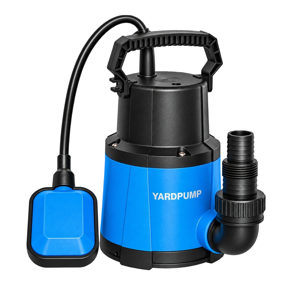
A pump passes at the factory but its curve appears lower at the importer’s laboratory. Before declaring nonconformity, establish whether both parties tested the same unit, revision and boundary conditions. Testing separate pumps with the same model name mixes product variation with measurement variation.
A stable, identifiable transfer pump and an aligned procedure provide a more useful starting point.
Exchange raw measurements, not only curve images
Flow, pressure, level, speed, voltage, frequency and water temperature should be associated with the measurement time. For head, identify the calculation datum, pressure-tap positions, elevation differences and any applicable velocity-head treatment. Outlet gauge pressure alone may omit relevant inlet and geometric conditions.
Align units, gauge versus absolute pressure and flowmeter conversion. Record pipe diameters, straight lengths, valve settings, outlet accessories, submergence and air conditions. Measuring supply voltage at a distribution panel rather than at the pump also changes the electrical boundary. Rescaling a chart until two curves overlap is not calibration.
Use an A–B–A return sequence
Measure the same stable pump repeatedly at laboratory A, transfer it to B for the agreed procedure, then return it to A. Transport, cleaning, running-in or blockage may change the sample. If A’s before-and-after results differ, the whole discrepancy cannot simply be assigned to B.
If A remains stable and B is internally repeatable but offset, investigate systematic differences. Neither laboratory is automatically correct merely because its readings repeat well.
For illustration, suppose the head at an agreed flow is 8.0 metres at A, 7.6 metres at B and approximately 8.0 metres after return to A. This supports further investigation of rig or measurement differences. It does not prove B is wrong: both systems may have bias, or an installation condition may remain unaligned. These invented readings are not a test report or an acceptance tolerance.
| Pattern | Investigation direction | Premature conclusion to avoid |
|---|---|---|
| Poor repeatability within one rig | Stability, air, instruments and handling | Production batch variation |
| Similar offset across the curve | Datum, zero, calibration and processing | Deliberate overstatement |
| Difference increasing with flow | Taps, piping and flow-related error | A constant correction will suffice |
| Transfer sample changes on return | Sample state and transport | One laboratory alone is responsible |
Calibration is necessary but not the whole measurement system
Installation, selected range, resolution, zero setting and processing can influence an instrument that has a valid calibration record. Stable readings during one short run do not establish consistency across days or operators. Examine short-term repeatability separately from longer-term and cross-system differences.
Competent laboratory or metrology personnel may need to assess uncertainty and the contributions that matter for the comparison. Do not combine all differences into an unsupported “test error” allowance.
If speed or other condition corrections are used, confirm their scope, algorithm and original measurements. A theoretical scaling relationship cannot legitimately correct every abnormal point into compliance. Air entrainment, significant cavitation, overheating and unstable operation require investigation rather than inclusion as ordinary curve points.
Return to contractual acceptance after correlation
Record resolved differences, remaining boundary gaps and residual uncertainty. Then apply the method and decision rule already agreed in the contract. Do not widen tolerances after seeing the result. Where adequate agreement cannot be established, use the agreed independent laboratory or reference installation and state the scope of that decision.
The final comparison should retain pump identity, A’s initial measurements, B’s measurements, A’s return measurements and every justified correction. Recheck correlation after replacing instruments, altering piping or changing processing software. A relationship demonstrated for one range and pump arrangement cannot automatically qualify another.
Align cleaning and handling of the transfer pump as well as the rig. Removing deposits at only one laboratory changes the sample. Where conditions cannot be aligned, document the difference and its likely influence before continuing. Do not fill missing inlet-pressure or speed fields with invented measurements simply to complete the comparison table.
Frequently asked questions
Should calibrated instruments guarantee identical curves?
No. Installation, calculation, handling and sample condition remain part of the measurement chain.
Can a fixed five-percent adjustment be applied to all customer readings?
Not without evidence. Establish the source and scope of any correction, and preserve the uncorrected data.
Can three new pumps tested once replace a return test of the same sample?
Not fully. Unit-to-unit variation would remain mixed with the rig effect.