Consider an installation example. A level sensor attached outside a plastic tank works on the original vessel but reports “water present” continuously on its replacement. Should sensitivity simply be reduced? If the identified model supports capacitive sensing through a vessel wall, first review wall material and thickness, mounting gap, nearby metal and internal deposits. Then follow its approved setting and validation method.
Without model documentation, do not treat every non-contact level switch as the same technology. Success on one plastic container does not establish suitability for every other one.
The sensor responds to its surroundings as well as the water
Capacitive sensing depends on electrical field conditions. The target liquid's dielectric behaviour influences the signal, but so can the vessel wall, an air gap, mounting hardware and nearby objects.
Think of distinguishing a change through an intervening layer. When that layer changes, the original decision conditions may no longer apply. “Both tanks are plastic” is not a sufficient material specification.
Resin, reinforcement, colour formulation and local thickness can differ. Ribs, curvature and raised features may prevent the sensing face from fitting as intended. A sensor that looks firmly attached does not necessarily have a uniform effective gap.
Validate empty and filled conditions
Adjusting a sensor until its indicator lights on a full tank does not demonstrate reliable empty detection. An internal liquid film, deposits or external moisture may change the empty-state response.
Some models provide particular build-up compensation or diagnostics. Their capabilities differ. Neither “all capacitive sensors fail with deposits” nor “compensation removes every deposit effect” is a sound general rule.
| Change | Conditions to record | Why it matters |
|---|---|---|
| Vessel wall | Material, local thickness, curvature and ribs | Alters through-wall conditions |
| Mounting | Gap, bracket, contact and nearby metal | Changes the sensing background |
| Liquid | Composition, temperature, foam and level | Affects target signal and transition |
| Service condition | Films, scale and external moisture | May affect empty detection and reset |
Use the actual manufacturer's requirements for mounting and any grounding or equal-potential arrangements. Do not copy another product's wall-thickness limit, sensing distance or wiring instructions.
Compare the installation combinations
As a hypothetical example, the original location has a three-millimetre wall, while the replacement has a six-millimetre wall and an additional rib. Those numbers illustrate a change; they are not recommended limits for any sensor.
Check empty, full, slow transitions through the detection position and the condition after draining on each arrangement. One illuminated indicator is insufficient. If location, bracket or settings change, preserve the initial configuration and the modification record.
After adjustment, validate the intended liquid range, temperature and relevant deposit conditions. A setting close to persistent false operation should not be accepted simply because one sample can be made to switch.
A detection signal is not a complete motor controller
Sensor outputs can use different electrical interfaces and logic. Detecting liquid does not establish the ability to switch a pump motor directly. Confirm supply, output type, switching direction, load interface and fault behaviour together.
Qualified personnel should carry out wiring or control changes after isolation using approved documentation. Controlled functional tests still need overflow, dry-running and personnel precautions. Bypassing a protective function to hide an unstable signal is not a correction.
The control system should also distinguish an actual level change from an identifiable sensor or wiring fault where the design provides that capability.
Freeze the verified mounting arrangement
Connect the tank, sensor model, mounting position and liquid limits to the approved sample and instructions. A different tank supplier or mould revision that changes wall construction may require renewed functional evaluation even if the container still fits its packaging.
For an unattended installation with serious flooding or dry-running consequences, assess independent limits, alarms or appropriate time-based supervision separately. A successful level transition does not cover future deposits, mounting movement or every wiring failure.
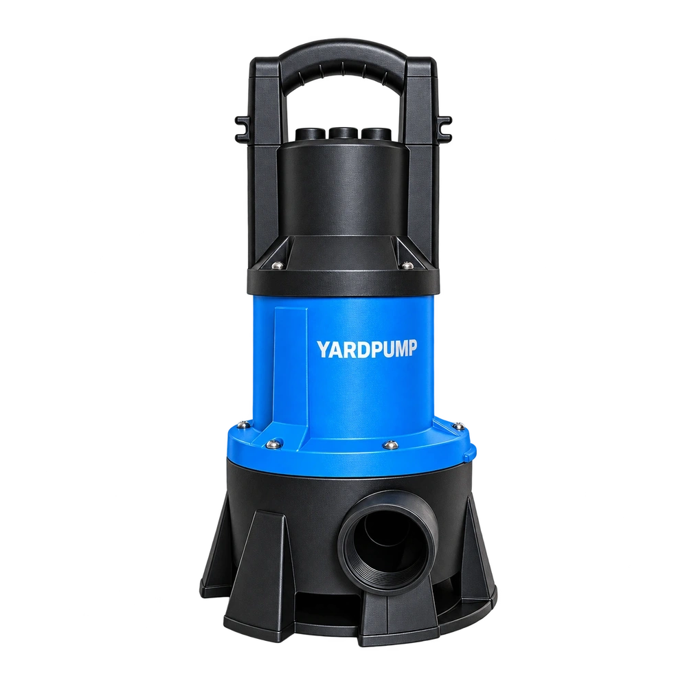
This article explains a selection and validation method. It does not identify the principle of an unknown photographed switch or establish that every YARDPUMP model uses capacitive sensing.
Frequently asked questions
Why recheck when both tanks are plastic?
Material, local thickness, curvature and sensing gap may differ, changing the complete sensing arrangement.
Is a full-tank indicator enough for approval?
No. Check empty detection, transition, reset after draining and the expected disturbance conditions.
Does build-up compensation remove the need for service-condition testing?
No. Compensation has defined limits and must be assessed with the actual liquid and deposits.