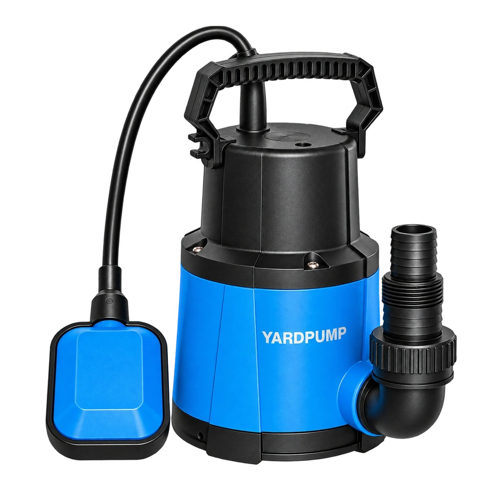
Suppose winding damage is found in a returned unit. The mark sits near a slot exit of a small submersible pump, even though the rotor turned freely. Could a stamped lamination edge matter? Yes. The rotor clearance is at the bore; the slot liner protects the winding from the steel within and around a slot. An edge that never touches the rotor can still press or cut the liner during insertion, winding or forming. A shiny lamination edge or a burnt spot alone does not prove which feature caused the failure. The location and the assembly sequence have to agree.
Keep the liner damage in its original position
Qualified staff should isolate the equipment and follow the procedure for stored energy before examination. Record slot number, end of the stack and direction. Distinguish a raised stamping edge from a step between laminations or damage from handling. Do not run a finger along an edge to find a burr. A long mark in the insertion direction may align with a slot mouth or guide surface. A local nick may align with a single step, a wedge edge or a fold. Heavy burning can erase the start of the damage. When needed, take a controlled destructive sample from the same batch that has not run, using the approved sampling process.
Imagine two samples with no rotor contact. One shows a repeated cut at the drive end fold of the liner in the second slot. Align that cut with the edge and check an unwound core and an assembly witness made through the same operations. This provides a more relevant comparison than measuring bore size again. If the second sample has marks at the same depth in several slots, examine the tooling and wire entry route as well. The illustration supplies no fault rate or universal burr allowance.
Identify the operation that first leaves a mark
Use the drawing or approval record to identify the location, direction and method for the edge inspection. Compare with approved parts. If punching direction matters, trace the direction through stacking and assembly. Review feed, die maintenance, liner material and projection, forming loads and the condition of guides. Inspect representative parts before lining, after lining and after winding where the quality plan allows. Finding the first stage at which a mark appears is better evidence than filing the edge afterwards. Do not grind an assembled winding without engineering approval. Tools and grinding debris can add damage or contamination.
For intake control, connect the steel core batch, tooling identity, liner lot and finished pump. After die maintenance or a liner change, ask for first article evidence from the relevant assembly stages. Set electrical retesting under the approved inspection procedure. A single electrical pass does not prove that there is no mechanical nick. A failed result likewise cannot be attributed to a burr without corroboration. If an ingress path, the test fixture or crushing in transit could explain the damage, keep those alternatives open while comparing samples.
The decision can then be narrow enough to act on. Contain the traceable lot while confirming a repeated insertion mark. If the position is unique to a return and no comparison evidence survives, keep the conclusion provisional. A clear record separates the inspection gate for the bore from the evidence gate for winding protection.
Give the slot number a starting mark and name the end from which it was counted.
Frequently asked questions
Can a passing bore gauge clear the slot mouth as well?
No. The bore gauge primarily checks rotor space. Slot edges also need a check appropriate to the liner and wire path.
Is a thicker slot liner a reliable fix?
Not on its own. Thickness affects available space and the insulation system. Locate the original damage and qualify the material or process change.
Why keep nearby units when only one pump has failed?
Unused units can help separate assembly damage from marks caused by a later failure. Use the quality plan for selection and release.