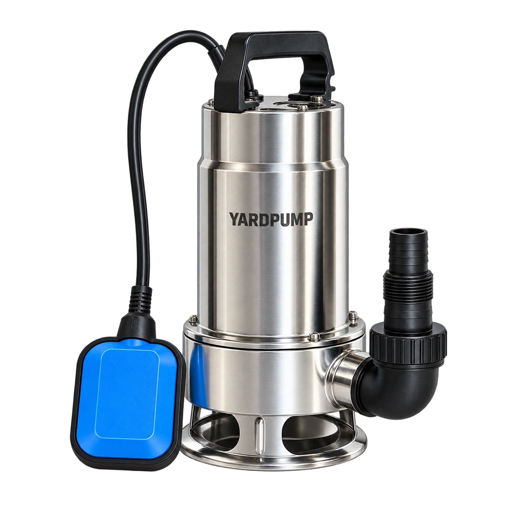
YARDPUMP BOM engineering
“Which impeller is the premium option—closed, semi-open, open or vortex?”
Wastewater and dirty-water pump manufacturers do not rank impellers by prestige. They select geometry from solids content, gas, sand, free passage and efficiency requirements.
Impeller geometry is a trade-off. More enclosed flow passages can support efficiency, while more open or free-flow geometries create more room for solids and gas at the cost of other hydraulic advantages.
Think of it like this
An impeller is both a fan and a hallway
The vanes add energy to the liquid, but the spaces between them are also the route that water and solids must travel through.
Narrow, controlled passages can use energy efficiently in suitable liquids. Larger open passages give debris more room but can sacrifice some hydraulic efficiency or balance.
That is why impeller selection is never just about “more blades” or “stronger material.”
A composite application mistake
The efficient clean-water impeller that became a debris trap
Imagine a pump chosen for strong clean-water efficiency but then used in a rain pit full of leaves and soft debris. The hydraulic design works beautifully until material bridges across the narrower passages.
The operator responds by increasing power or changing material, but the actual mismatch is geometry.
A more open or free-passage design may handle the dirty-water application better even if its clean-water efficiency is lower.
Free passage versus efficiency
Solids handling starts with the path through the impeller
KSB notes that free passage and efficiency are key impeller-selection variables in wastewater service. Fewer vanes can increase the unimpeded flow cross-section and improve handling of contaminated liquids and solids.
Closed impellers add a front shroud and can support controlled hydraulic passages, while open designs remove that shroud and create different solids and maintenance behavior.
Vortex or free-flow designs can keep more solids away from tight passages, but their hydraulic trade-offs have to be accepted deliberately.
Curve shape
Geometry changes where the pump prefers to work
Impeller diameter, width, vane count and blade shape all influence the relationship between flow and head. A high-flow utility pump and a higher-head multistage design therefore need different hydraulic geometry.
Changing the impeller without rechecking motor load and the Q–H curve can move the pump into a poor operating region.
For OEM work, impeller geometry belongs to the validated hydraulic set rather than to a casual BOM option.
What QC should watch
A visually correct impeller can still shift the pump curve
Molding shrinkage, machining variation, vane damage or a changed clearance can alter the hydraulic result even when the impeller looks like the approved part.
Golden-sample comparison, dimensional checks, balance where relevant and end-of-line performance testing make geometry measurable.
This is why a supplier substitution should be judged by the pump curve and current as well as by dimensions.
Where geometry labels stop
Open does not automatically mean dirty-water capable, and closed does not automatically mean efficient
The complete intake, casing, clearances, solids size, speed and liquid all matter. One word cannot describe the full hydraulic behavior.
Select the impeller as part of the whole hydraulic set for the intended liquid and duty.
Engineering decision layer
What to lock before you approve this component.
The narrative explains why the decision matters. This reference layer turns that reasoning into BOM, validation and supplier-control points.
- Open impeller — exposed vanes, easier passage/cleaning in some designs but sensitive to clearance and wear.
- Semi-open impeller — one shroud or partial enclosure, balancing efficiency, solids passage and serviceability.
- Closed impeller — shrouds on both sides, often efficient for clean liquids but less tolerant of large debris depending on passage design.
- Vortex / semi-vortex impeller — reduces direct contact between some solids and the impeller, often used for dirty-water reliability at an efficiency trade-off.
Geometry changes tooling, machining and casing complexity more than raw material cost alone. A high-efficiency enclosed hydraulic set can require tighter tolerances.
Impeller type drives the relationship among efficiency, clog resistance, free passage, head and flow curve shape. Grundfos wastewater ranges use different impellers specifically to trade these properties.
Wear and clearance growth can reduce performance, especially in open/semi-open designs. Vortex designs can be robust against clogging but may sacrifice efficiency.
Failures include clogging, erosion, worn clearances, cracked vanes and hydraulic imbalance.
Inspect clearance, runout and balance; performance-test samples before and after endurance/solids exposure where the application requires it.
B2B buyers should request the actual Q–H curve, efficiency data where relevant, free-passage/solids limit and clogging validation rather than buying on impeller name alone.
Impeller geometry and volute are a matched hydraulic set and cannot be changed independently without testing.
YARDPUMP expert takeaway
Do not rank impeller geometries as good, better and best. Choose the hydraulic path that fits the liquid, then validate the curve, motor load and solids behavior as one system.