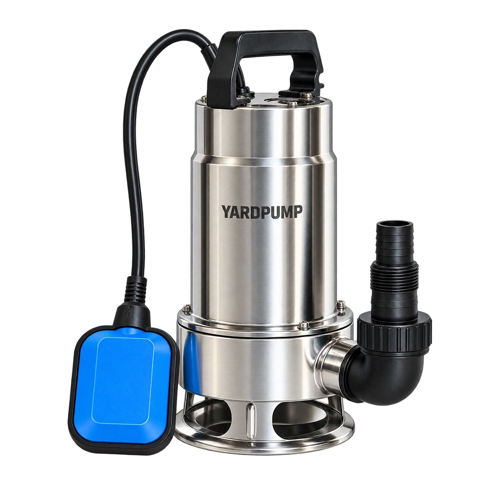
During a typical tank transfer, the source empties while the receiving tank fills. The pump sounds much the same, but delivery gradually falls. That observation does not by itself show a weakening motor. The changing water levels can increase system head throughout the job. Select and accept the installation for the complete transfer, rather than extrapolating from its initial flow.
Both surfaces can change the duty
When water moves between two open tanks and the delivery outlet remains submerged, static head is primarily the difference between their free water surfaces. A one-metre fall in the source combined with a one-metre rise in the receiver adds two metres of static head.
Unchanged hose diameter and length do not mean an unchanged operating point. Friction still depends on flow, while the static part of the system curve is moving. The intersection with the pump curve therefore changes as the transfer proceeds.
If the hose discharges freely into air above the receiver, the outlet section is normally the endpoint until the receiving liquid reaches and submerges it. A closed pressurised vessel needs its gas pressure included. These boundary conditions should be settled before calculations begin.
Check the beginning and end first
Consider an illustrative installation, not product performance data. Static head increases from one metre initially to three metres at the end. With its actual hose, a hypothetical pump might deliver four cubic metres per hour early in the transfer and 2.5 cubic metres per hour late in the job.
It would be misleading to promise a thirty-minute transfer of two cubic metres using the initial four-cubic-metre-per-hour figure alone. A staged estimate can be more useful. If the first cubic metre averages 3.75 cubic metres per hour and the second averages 2.75, total time is approximately thirty-eight minutes.
Those average flows are assumptions for the example. More calculation stages improve a model only when the pump curve, pipe losses and tank geometry are sufficiently reliable. Otherwise, extra decimal places simply conceal uncertain inputs.
The final part may control selection
Check that the highest static head plus losses at the required flow remains within the pump's permitted operating range. Maximum head is a near-zero-flow endpoint, not a promise to deliver maximum flow at that height.
If the final condition approaches that endpoint, the last part of the transfer can become disproportionately slow. The pump may also reach its low-water stopping condition before the desired source volume has moved. Minimum submergence, cooling and air intake therefore need assessment at the end of the job as well as the start.
Receiving-side protection is a separate function. A float attached to a pump in the source generally responds to the source water level; it does not know that a remote receiving tank is full. Arrange appropriate full-tank stopping or overflow protection for the actual system. Do not assume an unattended transfer is protected merely because the pump has a float.
Give the supplier a complete level specification
State both tanks' starting and finishing water levels, whether the outlet is submerged, the transfer volume and the required completion time. Add hose dimensions, fittings and the intended control arrangement.
For a non-cylindrical tank, equal changes in level do not necessarily represent equal volumes. Supply a level-volume relationship if it materially affects the estimate, or validate the entire transfer directly.
During acceptance, record flow, water levels and input power at the beginning, middle and end. Then check total transferred volume and elapsed time. If delivery falls much further than the changing duty predicts, investigate additional restrictions, air entry, valve changes or supply problems. Establishing the expected change makes an actual fault easier to recognise.
Tank cross-sectional area connects transferred volume with changing elevation. For each volume increment, calculate source-level fall and receiver-level rise separately, then combine them. This links tank geometry to the changing system curve. Keep the hose endpoint fixed or record its movement; otherwise, two complete-transfer times may describe different hydraulic tasks even when the nominal transferred volume is identical.
Questions about tank transfer
Would lowering the pump deeper restore the final flow?
It generally does not remove the difference between the two water surfaces. Immersion and cooling limits still apply, but pump-body elevation is not the only head reference.
Would a wider receiving tank help?
The same volume may produce less surface rise, reducing the change in static head. Include the source level and pipework before deciding whether that benefit matters.
Can one average water level be used?
It can support a preliminary estimate. Use staged calculations and a complete transfer test when the duty approaches a curve endpoint, tank geometry is complex or completion time is critical.