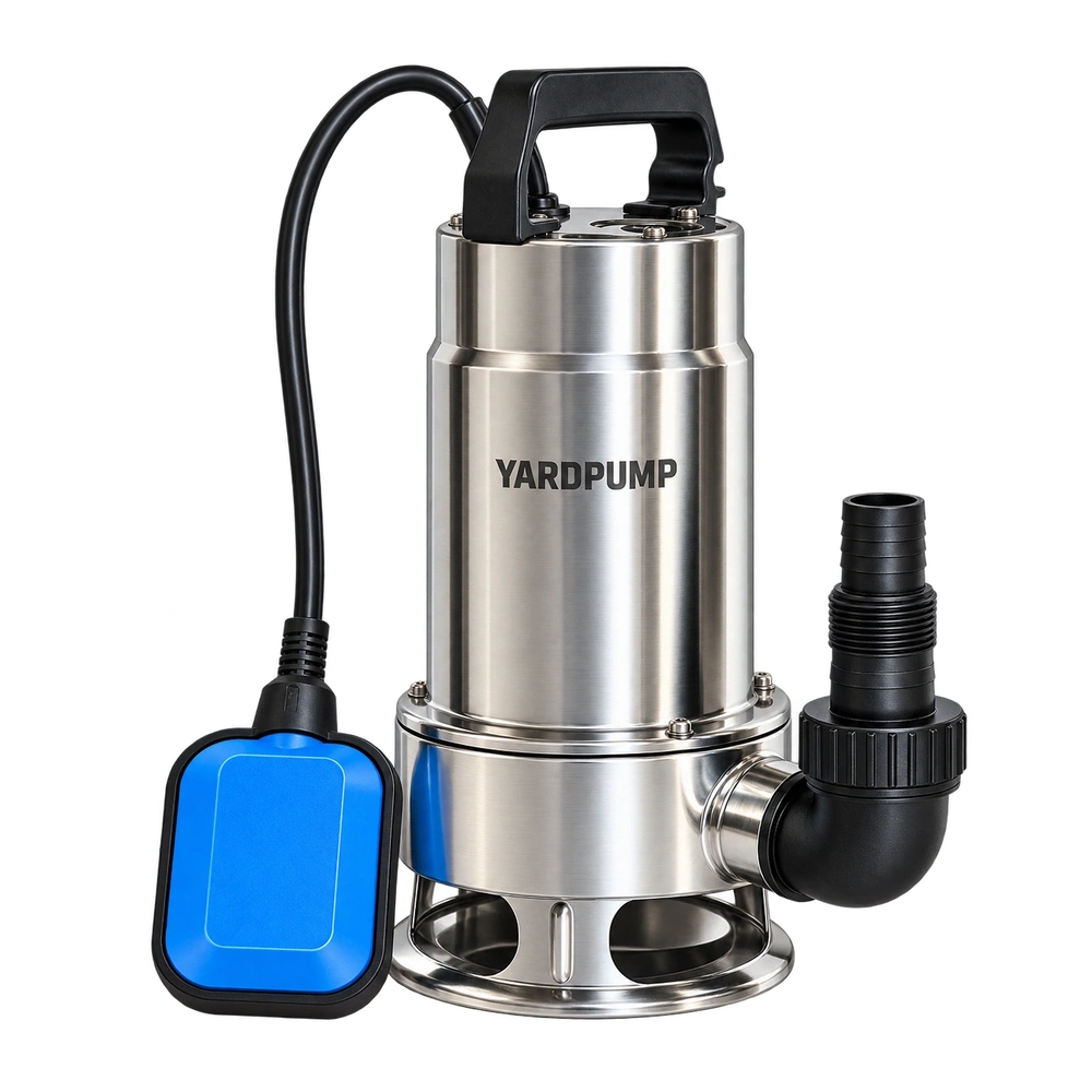
Imagine two single-phase submersible motors have acceptable cold winding resistance. After repeated operation, one develops a warmer region near a termination. Start by separating the winding from the connection in the investigation. The long winding can dominate the measured resistance and mask a much smaller resistance concentrated at one joint. A single room-temperature continuity check cannot show whether the termination will remain stable through heat cycles.
Conductor material is only one part of the joint
The aluminium surface, terminal design, pairing of metals and connection process can all affect electrical contact. Materials expand and contract as temperature changes. In some designs repeated cycling, loading or relaxation can alter the contact condition. Aluminium alone does not prove that a joint will fail. A copper-winding terminal that looks similar is also not evidence that the parts can be mixed. Verify the parts, tools, approved process window and protection for the actual conductor and termination.
Qualified personnel should use the approved bench and test procedure. If the joint boundaries can be accessed, define the measurement points, test leads, temperature and reading conditions. Four-wire resistance measurement may be appropriate for small values. If the reading also includes a length of conductor or terminal, document that boundary. Compare cold results at a consistent temperature rather than treating a still-warm winding as a degraded joint. Isolate and verify the equipment and address stored energy as required before electrical work. Use approved enclosed points for observations during operation.
Look for a repeatable change in the same place
For illustration, one joint measures five milliohms initially and 20 milliohms at the same temperature and points after cycling. If the operating current through that joint is four amperes in both cases, its ideal resistive loss rises from about 0.08 to 0.32 watts. That power is concentrated in a small area. These hypothetical values do not predict a temperature rise or pump life. If winding resistance remains stable but joint voltage drop and local temperature both change, that combination is more useful than total line current alone.
Record cold joint resistance, winding resistance at the same temperature, the loaded operating conditions and local temperature. Repeat after the approved cycling programme with samples representative of the actual material, terminals and process. If the entire winding is warmer, review load, cooling and the measurement method before blaming one connection. If the difference is local, investigate the connection process, stripped length, damage and contamination. Verify the original condition before considering any approved change.
Connect manufacturing evidence to the motor test
Lock the conductor, termination components, tooling and inspection conditions. Where the design requires it, check initial drop, mechanical retention and changes after the specified cycles. Compare the resulting thermal condition at the agreed electrical and hydraulic duty. The allowable change and cycle count come from the design and test agreement; there is no universal milliohm threshold here. If a return shows signs of local heating, stop use and preserve the joint. Do not add force, abrade it or apply a compound and then return it to wet service without a qualified decision.
The points themselves can change a result. If the first measurement includes a terminal tab and the second stops at a conductor, the resistance boundaries differ. Retain a point diagram and a known uncycled comparison part to help identify drift in the fixture or instrument.
Also record the time from shutdown to the reading. Differences in cooling can otherwise look like differences in the joint.
Frequently asked questions
Does a normal total winding resistance rule out a hot joint?
No. The total can conceal a small local resistance. Check the connection with a suitable boundary and method.
Is a higher reading taken while hot automatically a defect?
No. Conductor resistance depends on temperature. Align the temperature and measurement points before interpreting the change.
Can a similar copper terminal replace the original termination?
Only if the configuration and joining process are approved for the actual conductor. Appearance is not evidence of compatibility.