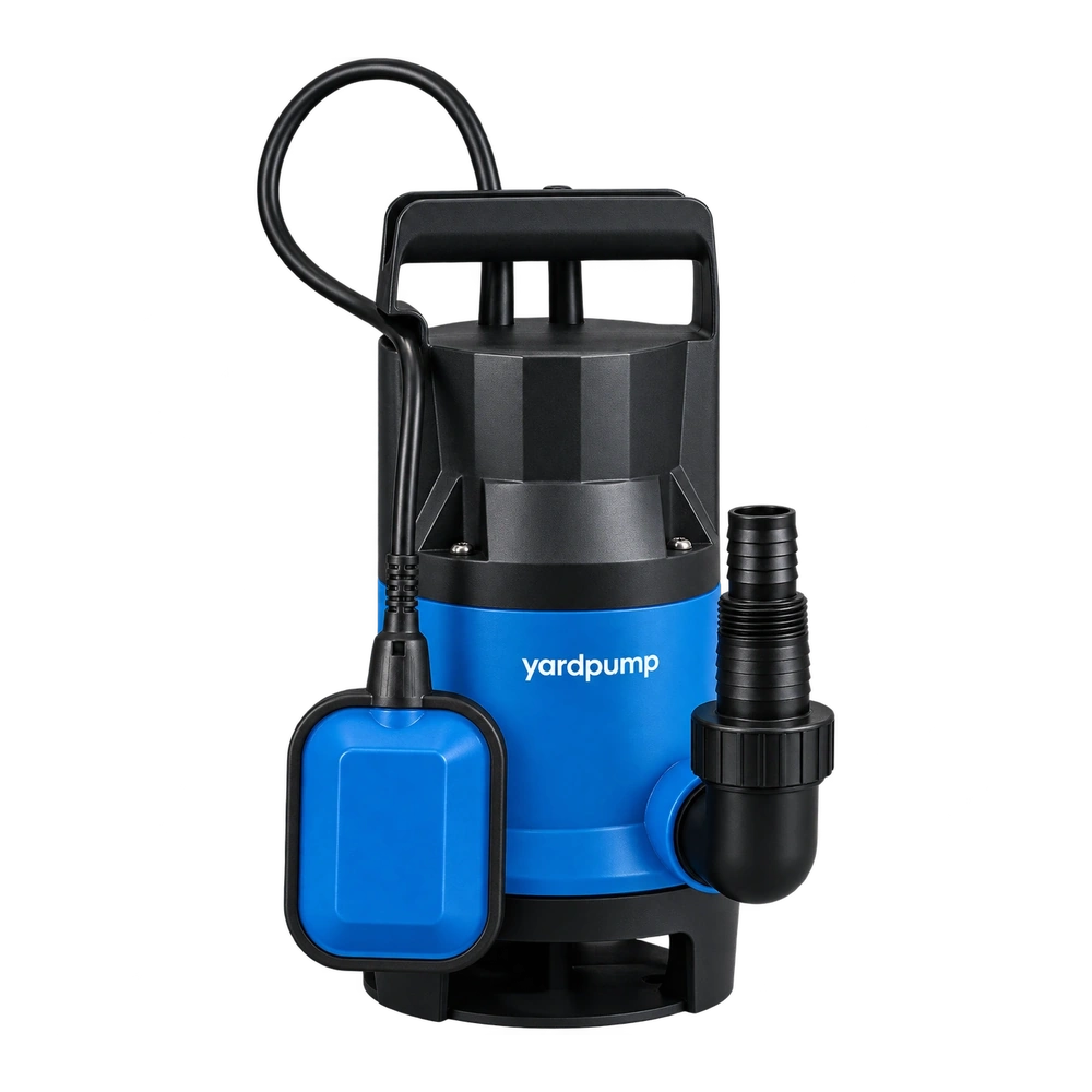
“Should the spring side of this radial lip seal face the water or the motor?” A distributor handling a returned submersible pump cannot answer that reliably without identifying the seal position. Conventional radial seals have a main sealing lip and an intended fluid side, but a pump may contain an oil chamber, opposing seals or a different lip arrangement. Seeing the spring does not establish the complete installation direction.
Draw both sides of the seal
First identify the exact seal location and the medium on each side. In an oil-chamber arrangement, the relevant fluid for one seal may be oil rather than external water. Another seal may perform a different task. A blanket instruction that every spring must face the water can therefore reverse a correctly designed arrangement.
Check the pressure relationships during operation and while stopped, including the possible direction of differential pressure. Correct orientation does not make an ordinary radial shaft seal suitable for arbitrary water pressure or reverse pressure. Shaft rotation and any directional lip features must also be checked against the particular seal documentation and approved pump design.
An auxiliary lip has a different purpose
Some seals include a dust lip or several visible contact edges. Their appearance can be mistaken for two equivalent pressure seals. The main lip, auxiliary lip and spring do not necessarily perform interchangeable functions. Identify them from the actual cross-section and product designation, rather than counting rubber edges and assuming bidirectional capability.
Two opposing seals introduce further questions about lubrication and the pressure in the space between them. Stacking two available seals back to back does not establish a validated sealing system. Orientation, spacing, lubricant provision and the contact locations on the shaft need to be considered together. The resulting assembly must match an approved arrangement, not an attractive sketch.
| Information to confirm | Why it affects installation |
|---|---|
| Full designation and lip cross-section | Identifies the main lip, auxiliary lip and limitations |
| Medium and pressure on each side | Establishes the leakage direction to control |
| Shaft rotation and surface requirements | Defines the working lip-to-shaft relationship |
| Installation depth and adjacent parts | Helps prevent interference or contact with an old wear track |
Correct orientation can still produce a faulty assembly
A shaft shoulder, keyway or unsuitable tool can damage the sealing edge. A tilted installation, changed depth, displaced spring or inappropriate lubricant can also create problems. Appropriate personnel should use the approved assembly procedure, protecting the lip and applying installation forces through the intended support surfaces. Looking level after hammering is not a useful acceptance method.
For a repair, inspect the actual shaft contact track. A correctly oriented new seal may still contact a wear groove, corrosion or scratches. Moving it to avoid that track can introduce interference or depart from the designed position. A technical assessment should establish the permitted repair rather than treating installation depth as a convenient adjustment.
Make production instructions unambiguous
Purchasing and incoming checks can require an assembly section with location numbers, medium identification, lip direction, installation depth and the associated seal designation. Directions such as “up” or “out” need an explicit reference. Turning the pump over on a bench should not change how the instruction is interpreted. An identified photograph can help, but it does not replace the section drawing and revision identity.
Consider a hypothetical documentation error. A repair sheet says “spring outward,” while a drawing is viewed from inside the motor. Neither defines outward. Two operators can follow the words and produce opposite results. Naming the medium side and showing the orientation removes the ambiguity more effectively than asking everyone to remember a local verbal convention.
Static tightness is only part of validation
A static leak test provides evidence for its stated conditions. It does not cover every effect of rotation, temperature, shaft movement and service differential pressure. An orientation correction or design change should receive the relevant verification for that model. One repaired pump that temporarily shows no visible leakage is not sufficient evidence to release a batch modification.
Frequently asked questions
Is “spring toward the fluid” enough as an instruction?
It can explain some conventional arrangements, but the actual seal designation, media on both sides and approved section still govern installation.
Do two visible lips guarantee pressure sealing in both directions?
No. An auxiliary lip is not necessarily another pressure seal with the same function. Check the documented construction and operating limits.
Is an operating check necessary after correcting the direction?
Verification should follow the applicable requirements. Rotation, temperature and shaft-contact problems may not appear in a static leak test.