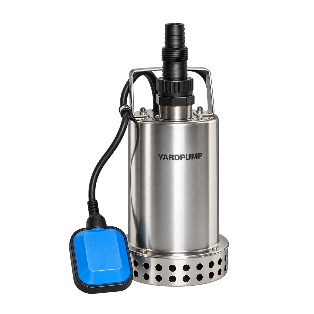
Can a motor and impeller originally intended for one rotation be converted to the opposite direction? Do not begin with the wiring. “Forward” and “reverse” may be ambiguous without a viewing position. Even a motor capable of reversing does not establish that the impeller, casing and retaining system suit the other direction. Treat a deliberate change of design rotation as an assembly redesign requiring validation.
Define the direction before changing anything
The same shaft appears clockwise from one end and counter-clockwise from the other. Mark the observer position, viewing axis and arrow on a sectional drawing. Distinguish actual observed rotation from required design rotation. The word “forward” can otherwise mean something different to the buyer, component supplier and assembler.
Correcting an incorrectly connected pump to its original specified rotation is one task. Developing an opposite-rotation version for sourcing or installation reasons is another. Restoring the correct electrical connection does not validate a new hydraulic design. Identify which task is being proposed before agreeing a test plan.
Reversible motor does not mean unrestricted rewiring
Three-phase induction motors and single-phase motors with auxiliary windings require different arrangements to change direction. Reversing the supply conductors of a single-phase pump generally does not reverse the motor. Whether its auxiliary-winding relationship can be changed depends on the accessible leads, starting arrangement and manufacturer's circuit. A sealed motor may offer no approved reconnection points.
Disconnect and isolate power before electrical work. Qualified personnel need the exact circuit and component information. Wire colours, trial connections, bypassed protection and live experimentation are not substitutes. Opening a sealed motor can also disturb insulation, cable sealing and assembly conditions, so the previous complete-pump acceptance cannot simply be assumed to remain valid.
The hydraulic assembly is not a mirrored photograph
Vane curvature, inlet edges and casing passages commonly have an intended direction. An incorrectly rotating impeller may still discharge water. That does not prove correct head, efficiency or pressure behaviour, and it does not justify retaining the old curve. An opposite-hand replacement impeller also needs a compatible casing arrangement.
Some manufacturer-confirmed symmetrical structures can support particular direction changes. Use their specific evidence rather than extending that possibility to all centrifugal pumps. Equally, apparently straight blades do not establish that the casing, sealing interfaces and axial loads are direction-independent.
| Interface | Review before conversion |
|---|---|
| Motor and control | Permitted direction, winding relationships and protection |
| Impeller and casing | Vane orientation, passages and complete performance curve |
| Shaft and retention | Threads, locking features and resistance to loosening |
| Seal and support | Direction-sensitive features, axial loading and temperature |
Check what the torque might loosen
Where a threaded or otherwise direction-sensitive connection retains the impeller, reversing torque can change the tendency to tighten or loosen. Review the actual torque path, retaining parts and assembly requirements. Checking that a nut currently feels tight is insufficient. Directional cooling features or pumping textures at a sealing interface may also require model-specific review.
This is an engineering assessment, not permission for a user to modify threads or add adhesive. An unvalidated locking method can introduce compatibility, maintenance and balance problems. Keep drawings and component revisions tied to the test sample so the final arrangement can be reproduced rather than reconstructed from photographs.
Release a tested configuration
The design review should state which parts remain, which change and why they match. Test flow and head, real electrical input, temperature, starting, vibration, noise and protection behaviour across the intended range, using the required liquid cooling and load conditions. Add sealing and endurance validation where the change warrants it. A brief dry spin does not replace a submerged assembly test.
For an illustrative acceptance scenario, the revised version must deliver the agreed flow at the agreed total head within predefined tolerances. Only then compare energy and thermal behaviour. No actual product performance is implied by this scenario. A new label without configuration-specific measurements leaves the conversion unverifiable. Any effect on certification coverage must be assessed against the applicable scheme and actual change; a general article cannot promise continued coverage.
Questions about changing rotation
Will swapping the two single-phase supply wires reverse it?
Generally no. Rotation depends on the motor winding and starting-circuit relationship. Qualified personnel need the manufacturer's information.
Is an opposite-hand impeller sufficient?
No. Review casing compatibility, axial position, retention, load and sealing, then validate the complete assembly.
Can the original curve remain if water still comes out?
No. Obtain performance evidence and operating limits for the revised configuration before releasing its documentation.