A replacement motor has two thin wires described as thermal-protection leads. Can they connect directly to the existing controller? First establish whether they belong to a thermostat contact, PTC thermistor or another sensor. Wire count does not define signal type. The sensing element, controller input and final shutdown circuit must work together.
Two wires can carry different information
A thermostat contact may open or close under specified conditions. Its controller responds to a switching state. A PTC thermistor provides information through its temperature-dependent resistance and normally requires a compatible detection arrangement. Other resistance-based temperature sensors use different characteristics again.
Two-wire devices are therefore not automatically interchangeable. Equal stated response temperatures do not establish equal interfaces. Sensor leads must not be treated as ordinary supply conductors, and mains voltage must not be applied to an unidentified sensing circuit.
A useful specification identifies the actual electrical function rather than relying on the convenient description “thermal wires.”
Check the complete protection chain
Start with the motor documentation: element type, wiring diagram, permitted measurement conditions and corresponding control equipment. Establish whether the controller expects a normally closed contact, normally open contact or specified resistance signal. Then verify how its output stops the pump, raises an alarm and permits resetting.
In a hypothetical replacement, the old motor uses a normally closed thermostat while the new one uses a PTC element. Both expose two thin leads. Copying the old connection can make the controller misinterpret the new signal. Bridging the input to keep the motor running bypasses an unresolved protective function and is not an acceptable solution.
| Element or stage | Information required | Insufficient identification |
|---|---|---|
| Thermostat contact | Contact logic and permitted load | Two visible wires |
| PTC element | Type, characteristic and compatible input | A temperature marking alone |
| Other temperature sensor | Characteristic and controller requirements | One cold resistance reading |
| Shutdown output | Switching, alarm and reset relationship | A normal panel display |
Cold measurements answer limited questions
A resistance or continuity reading may support identification. It cannot independently establish the response threshold, sensor location, controller compatibility or final shutdown function. The instrument's applied conditions must also suit the component.
Do not apply a general insulation or dielectric test indiscriminately to sensitive sensor terminals. Use the approved test arrangement and the component manufacturer's limits. Electrical investigation requires isolation, verification of a safe condition and management of stored energy by qualified personnel.
Where functional testing is required, use a controlled method. Deliberately stalling a motor or dry-running a submersible pump outside its instructions is not an appropriate way to test thermal protection.
Include wiring faults and restart behaviour
Once the interface is matched, assess how the system responds to an open sensor circuit, short circuit or poor connection. Controllers differ in diagnostic capability. A two-wire loop should not be assumed to detect every possible fault.
Decide which responses the application requires and verify them explicitly. Do not add an undocumented monitoring claim to the manual merely because a thermal element is present.
Also establish whether temperature recovery causes automatic restart or a latched alarm requiring manual reset. A stopped pump remains potentially energised. Cleaning and repair require electrical isolation; the reset logic is not a substitute for a maintenance lockout procedure.
Purchase and release a matched arrangement
When the motor or sensing element changes, retain the sensor identity, controller-input revision, wiring and functional-test results as one configuration. A quotation saying only “with thermal protection” leaves the interface unresolved. State what signal is provided and what external equipment it needs.
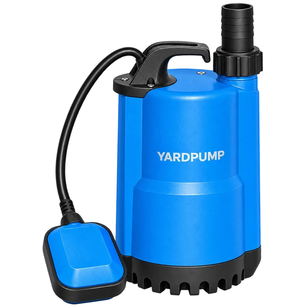
This discussion does not imply that every YARDPUMP product has an external PTC circuit, separate thermal leads or identical reset behaviour. Verify the actual electrical version before describing its functions to a customer.
Frequently asked questions
Can a PTC replace an ordinary thermostat contact directly?
Do not assume so. The detection input and shutdown circuit must be compatible.
Does a temperature display prove that shutdown works?
No. Indication, alarm and final switching are separate stages requiring verification.
Will a broken sensor wire always stop the pump safely?
That depends on the interface and control logic. Check and test the specific arrangement.