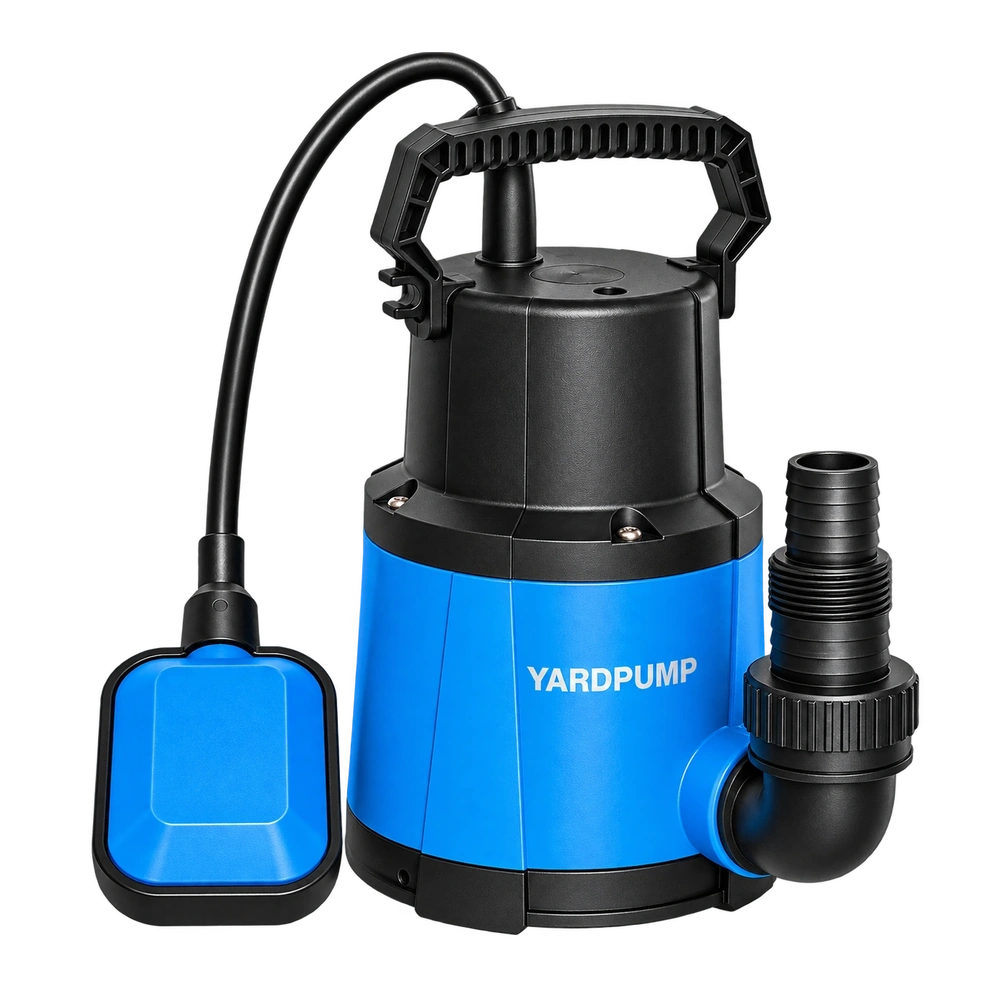
A utility pump worked in one corner of a tank. After being isolated, lifted and set down in another corner, it starts but delivers little or no water. The move can let air into the pump housing or change the high points in the hose. A flooded inlet and a route that lets air escape are the first things to check.
Air has to leave when water enters the housing
A centrifugal impeller transfers far less energy to an air pocket than to a water-filled passage. A discharge loop can retain air, while falling source level can draw a vortex into the inlet. Some designs include an anti-airlock path that must remain clear.
A pump that has just been moved can have water around its intake while air sits inside the volute. A water-filled riser above a check valve can hold back air leaving the pump. A flexible hose raised over a tank bracket can gain a high loop that was absent in the old position. Draw the old and new outlet angles on a simple sketch. Circle the first high point and any valve.
Air drawn in repeatedly looks different. If delivery starts and fades only as the tank gets shallow, watch for the inlet becoming exposed, a vortex or turbulence from return water. A brief burp on the first start and a repeated loss of flow at the same low level deserve different checks.
Compare the new route with an approved reference
Isolate power, let pressure decay and inspect hose routing, pump orientation, inlet submergence and any approved vent opening. Refill and restart only by the documented sequence. Compare with a short route that rises continuously without an air-trapping loop.
For example, if the short rising hose restores stable flow while the looped hose repeatedly loses delivery, the route is strong evidence. It does not establish that every no-flow event is airlock.
Make the comparison at the same water depth and with the approved pump position. Secure a test hose and keep its discharge where water can be handled safely. Note whether water arrives promptly, whether you see bubbles followed by steady flow, and whether the result repeats on the next cold start. A shorter route also reduces hydraulic resistance. If the result is ambiguous, fix the loop and compare with the same length and fittings before concluding that air alone caused it.
Use the vent the pump was designed to have
Release a route and installation that self-vents as intended and stays within the pump’s immersion and position limits. Clean only serviceable vent features by the approved method.
If the pump or installation has a specified vent, check its position and condition with the pump isolated and the discharge safely depressurised. Follow the manual for cleaning or repair. Take a photo of the installed hose geometry so it can be reproduced after maintenance. A pump left in a different position or a hose returned to a tighter bend can bring back the problem.
A broken impeller connection, clogged inlet or reversed valve can mimic airlock. Preserve the symptom and test one change at a time.
Frequently asked questions
Can I tilt the pump to let the air out?
Use only the orientation and priming procedure specified by the manufacturer. Isolate power before you reposition the pump. An improvised tilt during running can expose the intake or interfere with the control.
Should I drill an anti-airlock hole?
Follow the model’s approved provisions and installation instructions. On units without a specified field modification, ask the supplier how the setup is intended to vent.
Does an air bubble at the outlet mean the pump is faulty?
A bubble at a restart can be normal if flow becomes steady within the allowed startup sequence. Repeated loss of delivery is the symptom to investigate.