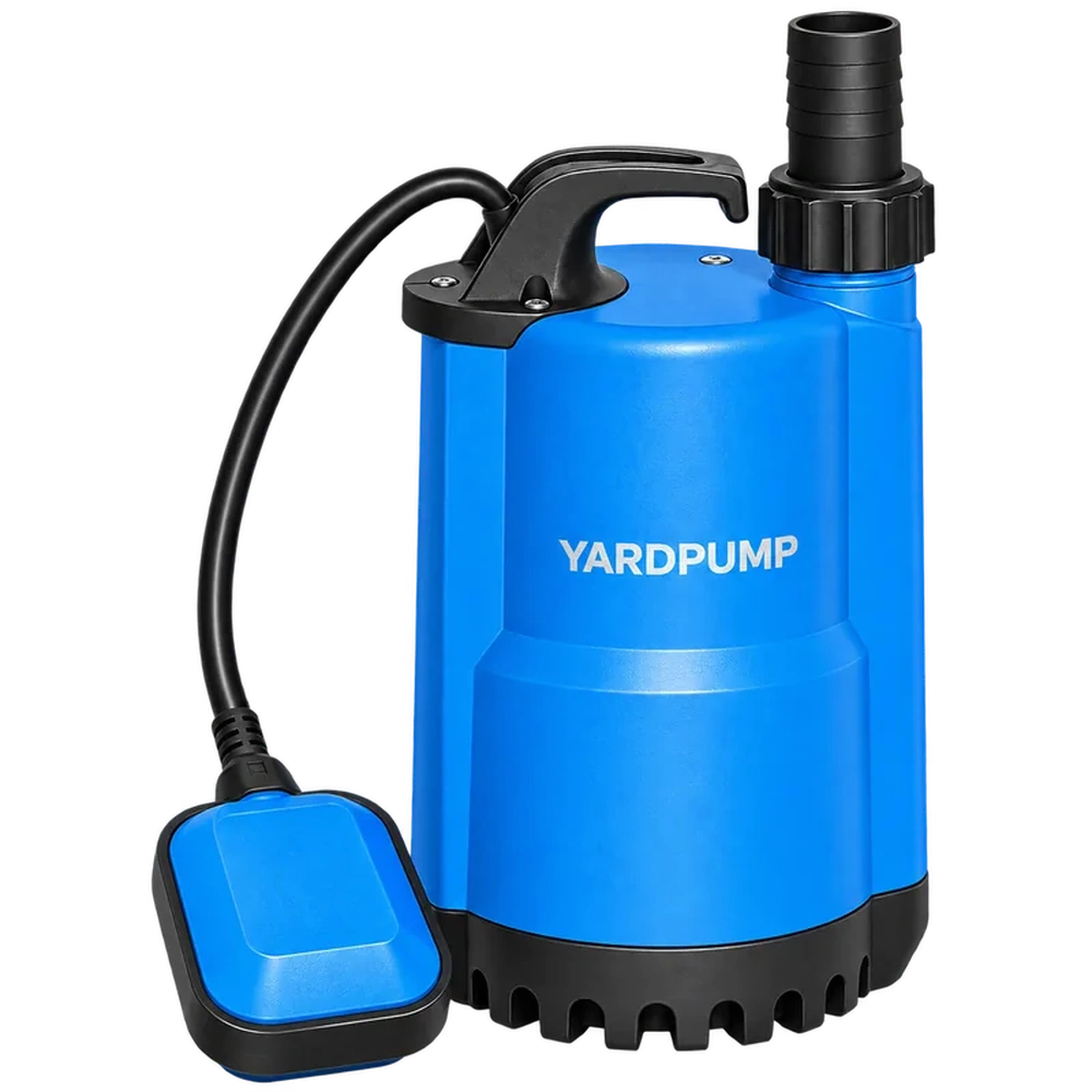
“The pump is submerged five metres and has fifteen metres of head. Does its shaft seal therefore face twenty metres of water pressure?” The two numbers cannot simply be added. A seal experiences the difference between the actual pressures on its two sides. External hydrostatic pressure, local hydraulic pressure and oil- or motor-chamber pressure must be assigned to the specific seal arrangement.
Draw the two sides of each seal
Start with the pump section drawing. Does one face contact the pumped liquid or an oil chamber? Does the other face connect to the motor cavity, another chamber or the external environment? A two-seal arrangement can expose each seal to different fluids and pressure differences. There is no universal rule that each seal takes half the total pressure.
The pumped-liquid side is not necessarily at discharge pressure. Impeller-back geometry, balancing passages, leakage paths and clearances can affect local chamber pressure. External water level and operating point also matter. Establish the relevant pressure from the actual structure and suitable validation, rather than assigning maximum pump head to every internal location.
| Quantity | What it helps describe | What it cannot establish alone |
|---|---|---|
| Immersion depth | External hydrostatic pressure | Complete differential across any seal |
| Pump head | Energy increase at an operating condition | Local seal-chamber pressure |
| Oil-chamber pressure | Boundary condition in that chamber | Pressure behind every seal |
| Allowable pressure | A specified component's design limit | Actual operating pressure |
Use a consistent pressure reference
Gauge pressure is referenced to local atmospheric pressure. Absolute pressure is referenced to vacuum. Do not subtract values using different references without conversion. Measurement elevation, velocity and tapping location also matter when comparing points. Define the interface under investigation before calculating a pressure difference.
For a static calculation example, assume water density of 1,000 kg/m³ and gravitational acceleration of 9.81 m/s². Five metres below a free surface corresponds to approximately 49 kPa of hydrostatic gauge pressure. Fifteen metres of water head corresponds to approximately 147 kPa. Those conversions do not establish that a particular seal faces 196 kPa. The seal location, pressure connections and operating state remain unknown.
A numerical result can look authoritative while describing the wrong boundary. A useful calculation states which two pressures it represents, where they apply and what assumptions support them. If those details are unavailable, report the differential as unconfirmed.
Separate stopped, running and changing conditions
After stopping, local pressure may approach a hydrostatic condition. During starting and running, the internal flow field develops again. Outlet position, system backpressure and operating point can change the relevant local pressure. “No leak while stopped” is therefore not equivalent to validation under running conditions.
Temperature, filling condition and chamber design can also affect a closed oil chamber. Do not assume it always remains at zero gauge pressure. Changing oil quantity, venting or the seal arrangement to achieve an imagined pressure balance requires engineering approval; it is not an informal field adjustment.
Similarly, one successful operating point does not establish suitability at every immersion depth or system condition. The test envelope must match the intended service.
Ask for pressure-boundary evidence
A purchasing enquiry should identify the seal arrangement revision, fluids on each side, permitted duty and validated immersion conditions. Ask how chamber pressure was established and which temperatures, depths and working points were covered. A generic seal catalogue does not automatically describe the installed pump. Its maximum component pressure must not become an unsupported whole-pump promise.
For a leakage investigation, preserve water level, operating time, working condition, liquid temperature and the start-stop sequence. Evaluate pressure alongside wear, contamination, materials and assembly evidence. Greater immersion depth is one possible influence; it does not exclude other causes.
Intrusive inspection, pressure instrumentation and motor testing require isolation and qualified personnel working to an approved procedure. This article provides a way to define the question. It does not increase any model's permitted immersion depth or recommend a seal-pressure modification.
Frequently asked questions
Does a higher maximum head always mean a higher seal differential?
No. Seal position, internal connections and the actual working point determine the relevant pressures. Nameplate head alone is insufficient.
Do two mechanical seals divide pressure equally?
There is no universal equal split. Intermediate-chamber pressure and the arrangement of both seals determine their individual differentials.
Does passing a static immersion test prove leak-free operation in all conditions?
No. It demonstrates performance within that test's specified conditions. Running and changing conditions need appropriate validation as well.