Increasing the clearance around an impeller may improve tolerance to certain debris, but it can also increase internal recirculation and reduce hydraulic performance. Reducing the clearance may help control leakage in a suitable design, yet it can make the pump more sensitive to abrasive wear, deformation or trapped particles. Neither approach is automatically superior: the result depends on the complete impeller, casing, wear surface and liquid-handling design.
The gap is not the same as the solids rating
The visible distance between an impeller and the bottom plate is only one geometric feature. A particle must travel through the inlet, past the impeller and through the discharge path. The narrowest relevant passage, particle shape, concentration, abrasiveness and the way solids settle all influence the outcome.
A product advertised for a particular maximum particle size needs model-specific validation. A photograph showing a raised impeller is not proof that a hard particle of that diameter can pass reliably; similarly, a close-clearance impeller is not automatically unsuitable for every dirty-water application.
| Design factor | Possible benefit | Trade-off or verification need |
|---|---|---|
| Smaller impeller-to-wear-surface gap | Can reduce internal leakage in some designs | Sensitive to rubbing, wear and trapped debris |
| Larger gap | Can increase physical clearance for some particles | May increase recirculation and reduce head or flow |
| Vortex or recessed arrangement | May reduce direct contact with some solids | Hydraulic efficiency and operating curve may differ |
| Inlet screen and base geometry | Can limit entry of oversized debris | Can clog, and does not certify solids handling by itself |
| Material and wear surface | Can influence durability under abrasion | Needs compatibility with water chemistry and solids |
Why extra clearance can change performance
A centrifugal impeller adds energy to water. If part of the discharge-side flow returns internally through a clearance instead of leaving the pump, the useful delivered flow can decline. The effect is design- and operating-point dependent. It is incorrect to claim that lifting an impeller by a fixed number of millimetres always produces a predictable percentage loss: the surrounding flow path matters.
The opposite extreme is also undesirable. Very small clearances may become vulnerable to rubbing when tolerances stack up, parts expand with temperature, bearings wear or grit enters the gap. A pump that tests well with clean water when new may behave differently after abrasive service.
Evaluate the entire pump, not one dimension
For an OEM review, request the impeller type and material, sectional drawing, critical clearances and their tolerances, allowed solids size and concentration, expected liquid chemistry, the actual Q–H curve and any model-specific test evidence. Where the customer expects sand, fibres or heavy slurry, confirm whether the pump is designed for those materials at all; do not infer suitability from a “dirty water” label.
A useful comparison test controls the electrical version, water temperature, test setup and duty point. Record flow and head before and after any structural revision, plus power input, vibration or noise observations and wear condition where appropriate. Without such controlled evidence, a small change in geometry cannot be called an improvement simply because it sounds plausible.
What this means for distributors and buyers
Customers usually describe the problem as “it clogs,” “the flow is weaker,” or “the pump wears quickly.” These are different failure modes. First ask about water source, particle type, concentration, run time, inlet position and discharge hose. A blocked screen may reduce flow even if the impeller is undamaged; an abrasive liquid may accelerate wear even when particles pass through.
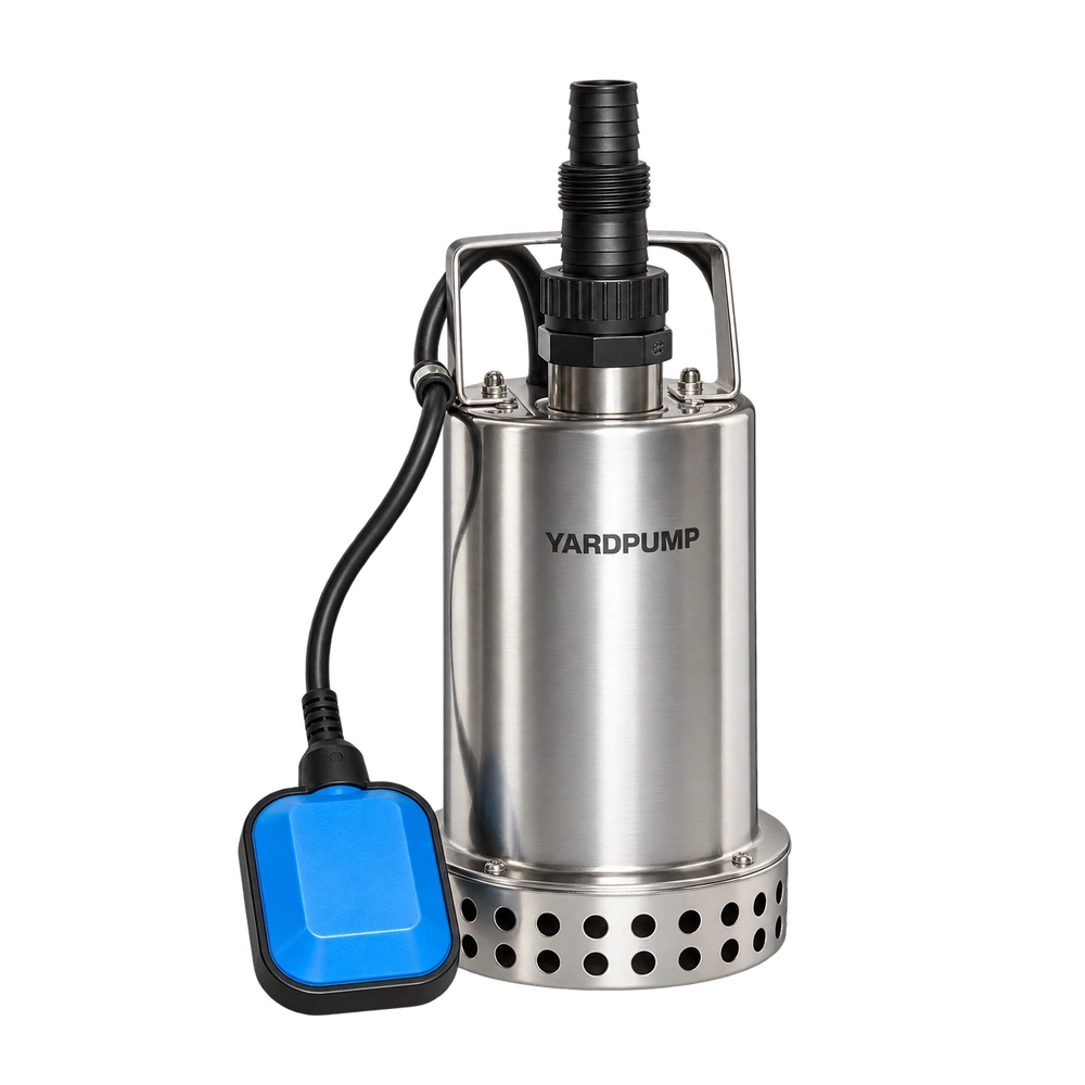
Compare model families using the technical article library. The WQD-SD product page is a verified YARDPUMP product reference for clean-and-dirty-water positioning, but its actual solids allowance and construction must be read from the approved model data, not inferred from this general article. Send the intended liquid and working duty to the technical inquiry page for a configuration review.
Engineering conclusion: The right question is not “Which gap is bigger?” but “Which complete hydraulic design delivers the required working performance and reliability in this liquid?”
FAQ
Does a taller impeller always produce more flow? No. Blade geometry, diameter, casing, rotational speed and operating point all matter.
Can a recessed impeller handle any size of solids? No. The whole passage and model-specific tested limits still govern.
Is a smaller gap always more efficient? Not always. Leakage, friction, manufacturing tolerances, wear and the full hydraulic geometry must be considered together.