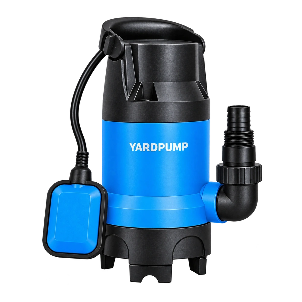
Consider an illustrative housing-return investigation. “The plastic pump housing cracked along a line. Is the mould joint defective?” First identify the line. A mould parting line, an injection-moulding weld line and a subsequently assembled or welded joint are different features. The correct identification determines whether to investigate flow and moulding, tooling, material or the joining process.
Three lines with different origins
A parting line is the surface trace where sections of the mould meet. Flash or mismatch may occur there. It marks a tooling boundary, but does not automatically indicate an internal interface between two meeting melt fronts. Excessive flash needs attention; a visible parting trace alone does not prove a leakage defect.
An injection-moulding weld line forms where separated flow fronts meet again. Holes, inserts, ribs and multiple gates can influence its location. Melt-front temperature, bonding, venting and reinforcement orientation can affect the properties of that region.
An assembly joint connects separately manufactured parts using screws, adhesive, welding or another joining method. Leakage along an ultrasonic weld therefore calls for different evidence from cracking along a moulding weld line. Similar terminology must not collapse those investigations into one.
Visibility is not a strength test
Some weld lines produce a colour or gloss difference, while others are difficult to see. Significance depends on the material, moulding quality, local stresses and specified performance. Making a line visually disappear is not proof of adequate strength. Equally, the existence of a visible line does not automatically make a complete batch unsuitable.
Reinforced plastics require attention to fibre orientation near converging flow. Adding ribs may improve stiffness in one direction while changing melt flow and the location of convergence. Simply increasing wall thickness may introduce shrinkage or other moulding issues without resolving the local weakness.
The assessment should therefore connect the feature to its loading and manufacturing conditions. Avoid selecting a material or process change solely because it produces a smoother-looking sample.
Preserve the evidence on returned housings
Isolate electrical power and keep the component intact. Record the crack origin and direction, internal and external surfaces, nearby screw bosses or pipe connections, and evidence of impact, pipe loading or chemical exposure. Include scale and orientation in photographs. An isolated close-up without location information is difficult to interpret.
Retain cavity identification, batch information, material identification and assembly records. A concentration of problems in one cavity or production interval can guide investigation, but should not be described as a general defect without appropriate evidence. Grinding, gluing or forcing a housing open can destroy the crack origin and fracture information.
Match the observation to the next investigation
| Observation | Priority checks | Unsupported conclusion to avoid |
|---|---|---|
| Crack near a flow-convergence region | Gates, venting, moulding window and local stress | Every weld line is defective |
| Crack close to a screw boss | Tightening, boss geometry and residual stress | A harder resin will necessarily solve it |
| Leakage at a separate welded joint | Joint design, cleanliness and welding process | It is the same issue as a moulding weld line |
| Crack with external loading marks | Pipe support, impact and installation forces | A factory leak test rules out structural problems |
Competent specialists may need fracture examination, sections, controlled moulding comparisons and representative structural tests. Flow simulation can help locate meeting fronts, but it does not replace validation of actual moulded parts. Tests should represent the approved temperature, liquid, pressure and external loading boundaries.
Write requirements that support OEM control
Identify critical load-bearing and sealing regions in drawings and approval records. Specify material grade, the policy for reprocessed material and change-control requirements. A new tool, cavity transfer, gate alteration or material change may require renewed confirmation according to risk. Comparing component weight alone cannot establish equivalence.
Production monitoring can combine visual checks, process records and validated performance sampling. Pressure or leakage testing requires approved test media, pressures and protective arrangements; operators should not improvise higher pressure to locate cracks.
If a problem appears, quarantine the relevant stock and trace its conditions before deciding whether the cause is process drift, a design boundary or external loading. The useful outcome is a demonstrated correction tied to the observed failure mechanism.
Frequently asked questions
Does grinding a parting line smooth improve strength?
It is generally an appearance operation, not proof of improved internal bonding or load capacity. Excessive removal can reduce local thickness, so follow the approved process.
Will increasing glass-fibre content eliminate weld-line cracking?
Not automatically. Fibre content and orientation, resin toughness, processing and part geometry interact. Validate the complete proposal.
If every pump passes a leak test, is structural endurance unnecessary?
No. A short leak test establishes sealing at that moment. Depending on risk, temperature exposure, repeated loading and crack growth still need separate validation.